Installation guide & product manual

Wall Top Climb Detection Sensor

Battery-free wireless climb detection for stable, structurally sound perimeter wall tops across common construction materials.

Battery-free433 MHz RFSurface mount600 × 150 × 25 mm
Product codeAG-PWT-100
SKUAG-PWT-100-BK
Document IDAG-PWT-100-MAN-EN-R01
Hardware revisionV.1
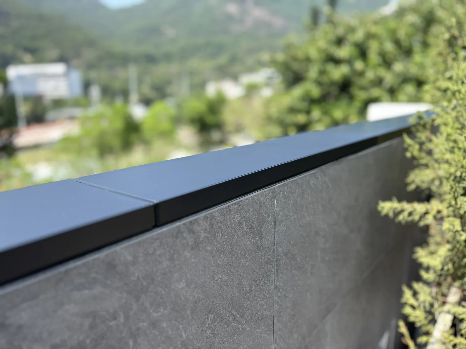
Apeiron Guard Wall Top Climb Detection Sensors installed continuously on a flat masonry perimeter wall
Standard and custom lengthsStandard 600 mm units and custom 300 mm or 200 mm units require at least 2 mm between adjacent sensors.

Product overview

Understand the intended system role and installation geometry before work begins.

What the Wall Top Sensor does

The Wall Top Climb Detection Sensor detects pressure from an attempted climb-over and transmits a wireless alarm event.

Its intended alarm response depends on the paired receiver, zone configuration and project design.

Installation covered by this guide

This guide covers straight wall-top runs using standard and custom sensor lengths, a minimum 2 mm inter-unit gap, structural-sealant bonding and onsite assessment of features that may prevent a safe installation.

Skill levelProfessional installer recommended
Product codeAG-PWT-100
MountingSurface mount
System requirementMini Alarm Hub or Wireless I/O Module

Package contents & tools

Confirm the production package and all required installation materials before release.

Package contents

  • 1 × Wall Top Climb Detection Sensor
  • Packaging-printed QR code linking to this installation manual

Required but not included

  • Compatible Apeiron Guard Mini Alarm Hub or Wireless I/O Module
  • Construction-grade structural sealant rated for exterior use and compatible with the sensor base and substrate
  • Surface-safe cleaner and lint-free materials
  • Straightedge, tape measure and temporary position markers
  • Manufacturer-approved sealant application tools and PPE
  • Site test and handover records

Safety & installation suitability

This product is part of a security system and does not replace physical protection or certified life-safety equipment.

Important height warningBecause the product is secured solely by a cured construction-sealant bond, Apeiron Guard does not recommend installation at a height of 3 m or above. Installation at this height may proceed only after a competent installer has completed and documented a full site-specific assessment of the mounting location, substrate condition, environmental exposure, falling-object risk and bonding suitability, and has determined that the product can be installed safely and securely. The installer remains responsible for the installation method and for compliance with all applicable work-at-height and safety requirements.

Do

  • Test the radio event at the proposed position before permanent mounting.
  • Concrete, brick, stone, tile, metal coping, painted surfaces and other substrate types may be used when the surface is stable, structurally sound, clean and compatible with the structural sealant.
  • Inspect coatings and surface layers for peeling, flaking, delamination or other loss of adhesion before installation.
  • Use only construction-grade structural sealant rated by its manufacturer for exterior use and compatible with both the sensor base and mounting substrate.
  • Keep the activation area unobstructed.
  • Verify repeated operation before handing over the system.
  • Follow the substrate and sealant manufacturers’ preparation, application and curing guidance.

Do not

  • Do not install on a surface that is peeling, flaking, loose, delaminating, unstable or likely to detach from the underlying structure.
  • Do not bridge or block drainage gaps or movement joints.
  • Do not assume installation is possible at corners, posts, level changes, drainage gaps or movement joints; assess each condition onsite and proceed only where a safe, stable installation is achievable.
  • Do not drill into, open, paint or modify the enclosure.
  • Do not reuse removed sealant or substitute an unapproved bonding system.
  • Do not rely on the maximum radio range without an on-site test.

Product anatomy

The supplied dimension diagram is the exact visual source for product geometry and scale.
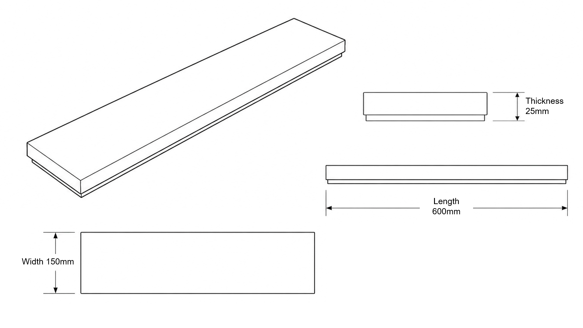
Approved technical dimension diagram for the Apeiron Guard Wall Top Climb Detection Sensor
Product anatomyKevin-approved 2000 × 1125 geometry reference
A
Pressure-sensitive topThe full upper surface forms the intended climb-over activation area.
B
Available sensor lengthsThe standard unit is 600 mm long; custom 300 mm and 200 mm units are available for shorter sections.
C
Stepped lower baseThe underside sits flat on the prepared wall cap and receives the approved bonding system.
D
Inter-unit spacingMaintain a minimum 2 mm gap between adjacent sensors.
E
Reference dimensionsStandard unit: 600 × 150 × 25 mm. Custom lengths: 300 mm and 200 mm.

Installation steps

Follow this sequence for an approved Wall Top Sensor installation.

1

Survey and mark the protected run

Confirm the wall top is flat, stable and structurally sound before planning sensor coverage.
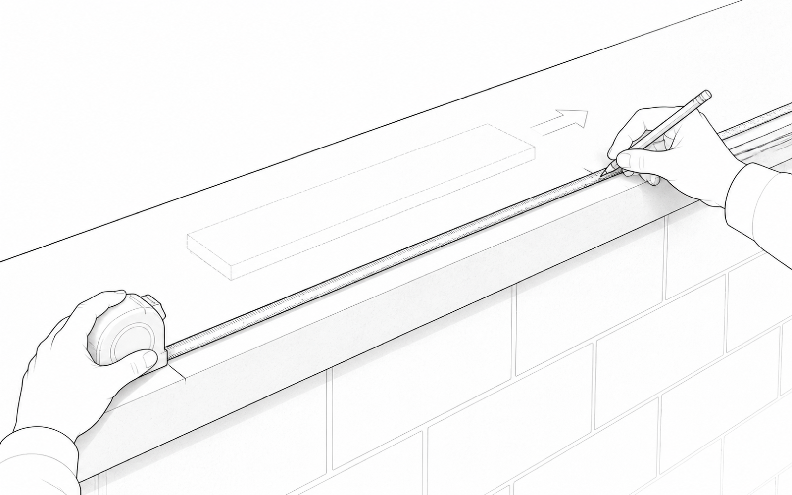
  • Concrete, brick, stone, tile, metal coping, painted surfaces and other materials are acceptable when stable and structurally sound.
  • Do not install over any surface layer that may peel, flake, delaminate or detach.
  • Assess corners, posts, level changes, drainage gaps and movement joints onsite; installation may not be possible unless the installer confirms a safe, stable detail.
Black-and-white installation illustration showing an installer measuring and marking a straight wall-top sensor run
2

Order the correct sensor lengths

Use standard 600 mm units for the main run and custom 300 mm or 200 mm units for shorter sections.
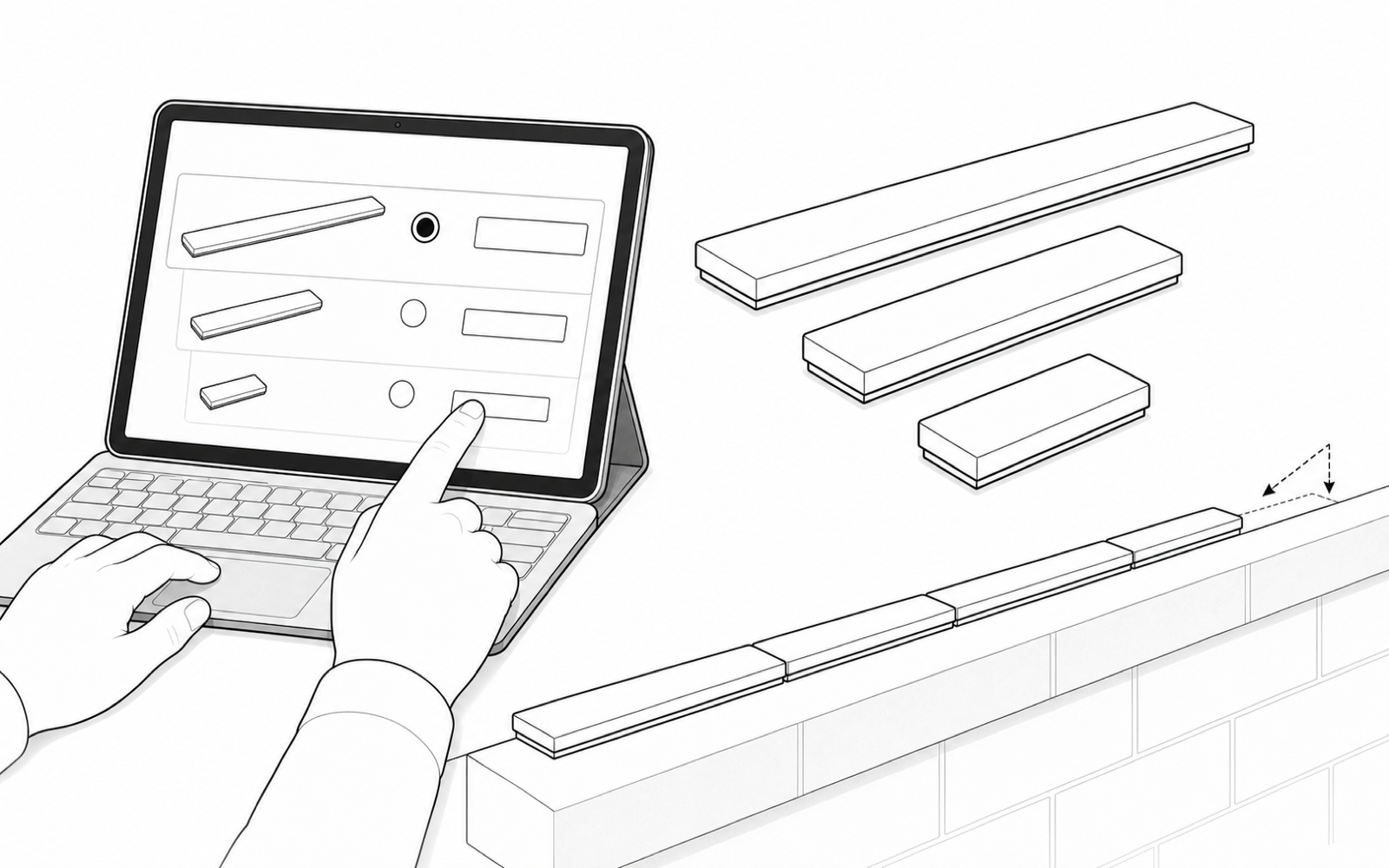
  • Measure the complete protected length.
  • Allow for a minimum 2 mm gap between every pair of adjacent sensors.
  • Confirm the complete unit schedule and quantities before ordering.
Black-and-white installation illustration showing an installer ordering standard and shorter Wall Top Sensor lengths to match a measured wall run
3

Prepare the mounting surface

Remove dust, grease, loose coatings and moisture using methods approved for the substrate and structural sealant.
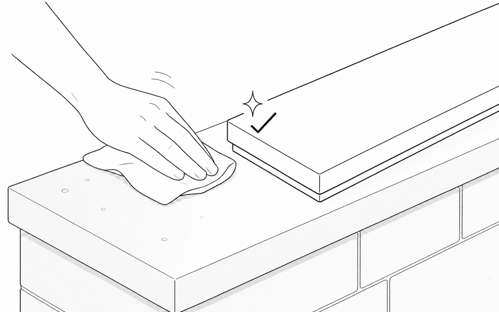
  • Remove or repair peeling, flaking, loose or delaminating surface material.
  • Allow the surface to dry fully.
  • Do not proceed unless the remaining mounting surface is stable and structurally sound.
Black-and-white installation illustration showing a wall-top mounting surface being wiped clean beside a correctly scaled sensor
4

Apply the approved structural sealant

Apply two or three straight lines of construction-grade structural sealant along the bottom of the sensor. The sealant must be rated for exterior use and compatible with both the sensor base and mounting substrate.
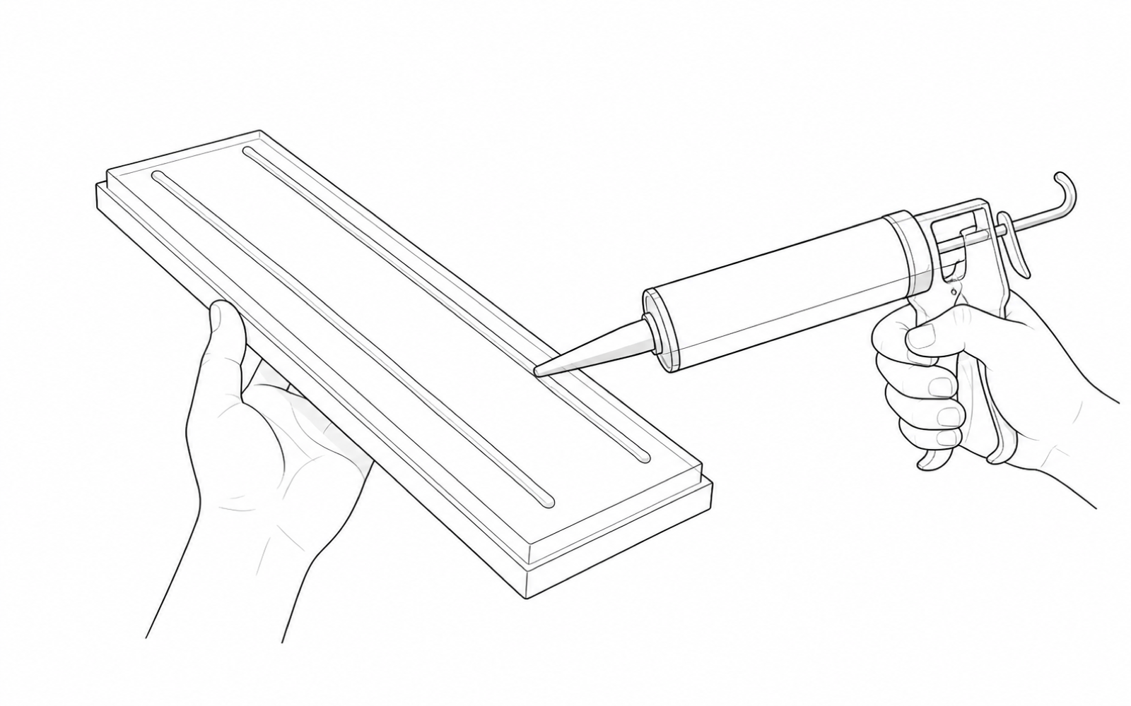
  • Follow the sealant manufacturer’s surface-preparation, PPE, application and curing guidance.
  • Do not block drainage gaps or movement joints.
  • Do not substitute screws, unapproved sealants or unapproved brackets.
Black-and-white installation illustration showing two approved structural-sealant beads applied to the Wall Top Sensor base
5

Place, space and secure each unit

Set each Wall Top Sensor onto the marked wall-top position and maintain a minimum 2 mm gap between adjacent sensors.
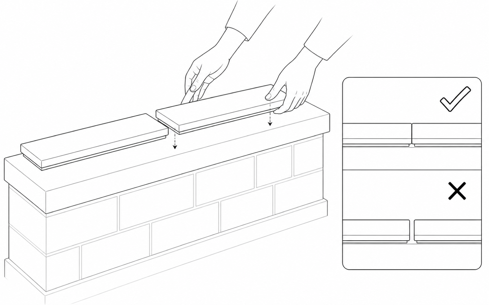
  • Keep each top face level and unobstructed.
  • Do not bridge site features that the installer has not assessed as suitable.
  • Prevent rain or water contact for 48 hours while the sealant cures.
Black-and-white installation illustration showing Wall Top Sensor units placed level with the required minimum 2 mm gap
6

Commission the complete run

After the bonding system has cured, trigger and test every installed unit from its final position with the paired hub or I/O module.
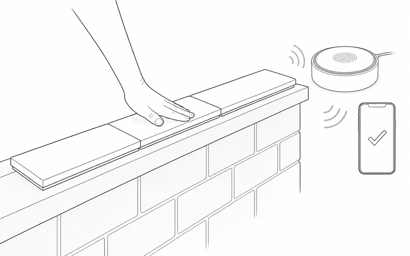
  • Verify the correct zone name.
  • Repeat each functional test at least three times.
  • Record installation photos and test results before handover.
Black-and-white installation illustration showing an installed Wall Top Sensor pressed and its wireless event confirmed by the Apeiron Mini Alarm Hub and phone

Pairing & commissioning

Complete the final approved system sequence before customer release.

Pair with the selected receiver

Follow the receiver-specific guide for enrollment, zone naming, success indications and removal.

  • Mini Alarm Hub and App setup guide
  • Wireless I/O Module: follow the project-specific wiring and commissioning documentation supplied with the module.
  • Pair and name one sensor at a time.
  • Complete commissioning before customer handover.

Commissioning test flow

01Enroll sensor
02Set zone name
03Trigger product
04Verify receiver

Do not hand over the installation until the complete event path works reliably from every final position.

Normal operation

Use these states to verify the physical product and connected-system response.

StateWall Top SensorExpected system behavior
Normal conditionThe Wall Top Sensor remains unobstructed on the protected solid wall top.No alarm event is generated.
Climb-over pressurePressure activates the self-powered sensing mechanism.A 433 MHz RF alarm event is transmitted.
Receiver gets eventNo local control is required at the sensor.Mini Alarm Hub or Wireless I/O Module response follows the configured zone rules.
After activationThe sensor automatically returns to its normal state.No reset, disarm or other action is required at the sensor.

Quick troubleshooting

Resolve installation, power and communication faults before replacing the product.

SymptomLikely causeAction
No event during activation testSensor not enrolled, receiver unavailable, weak RF path or incorrect mechanical activation.Test near the receiver, confirm enrollment and inspect the final installation geometry.
Intermittent alertsWeak radio conditions, metal shielding, unstable mounting or marginal activation.Repeat tests at the final position and correct mounting or receiver location.
False or repeated alertsMovement, obstruction, misalignment or unsuitable mounting surface.Inspect the protected point, remove interference and remount if required.
Adhesive begins liftingContaminated surface, insufficient cure, unsuitable substrate or incorrect adhesive.Remove safely, prepare again and remount using the approved bonding system.
Wrong device shownIncorrect zone naming during commissioning.Correct the device name and repeat the complete functional test.

Technical specifications

Current values from the approved datasheet and dimension diagram.

ItemValue
Product codeAG-PWT-100
Dimensions600 × 150 × 25 mm
Weight3.85 kg
Operating temperature-20°C to 55°C
Storage temperature-20°C to 55°C
Working humidity≤99% RH
PowerSelf-powered
Shell materialFRP
InstallationSurface mount
Transmission433 MHz RF
Transmission rangeUp to 80 m outdoors; up to 25 m indoors
Durability>100,000 cycles

Maintenance, support & disposal

Routine inspection and functional testing remain required throughout the system life.

Routine care

  • Test the product during scheduled security-system inspections and after nearby building work.
  • Check that the mounting system remains secure and correctly aligned.
  • Keep the activation area clean and unobstructed.
  • Clean only with methods approved for the product and substrate.
  • Replace cracked, deformed, loose or mechanically sticking products.

Support and end of life

  • Support: [email protected]
  • Quote AG-PWT-100, the hardware revision and AG-PWT-100-MAN-EN-R01 when requesting help.
  • Warranty terms and exclusions: One-year product warranty
  • Dispose of electronic products according to applicable local requirements.
  • The QR short URL must always resolve to the latest compatible guide.