What the Door Sensor does
The Door Sensor detects a door opening when the opposing block moves away and the activation button releases.
Its intended alarm response depends on the paired receiver, zone configuration and project design.
 Product Support
Installation guide & product manual
Battery-free wireless opening detection for compatible single, double-swing and double-sliding doors.

Understand the intended system role and installation geometry before work begins.
The Door Sensor detects a door opening when the opposing block moves away and the activation button releases.
Its intended alarm response depends on the paired receiver, zone configuration and project design.
This guide covers surface-mounted installation on single, double-swing and double-sliding doors. The mounting sides vary by door type, but the opposing block must fully press the activation button inward whenever the door is closed.
Confirm the approved package contents and prepare the required installation materials.
This product is part of a security system and does not replace physical protection or certified life-safety equipment.
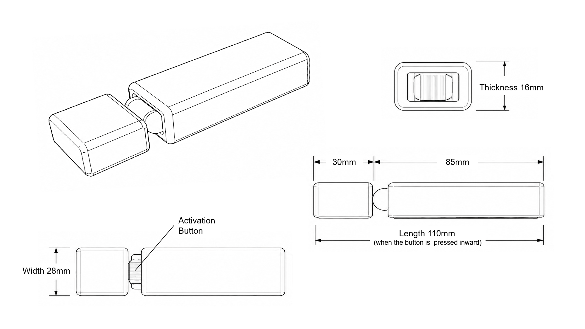
The supplied dimension diagram is the exact visual source for product geometry and scale.
Follow this five-step sequence for the approved Door Sensor installation.
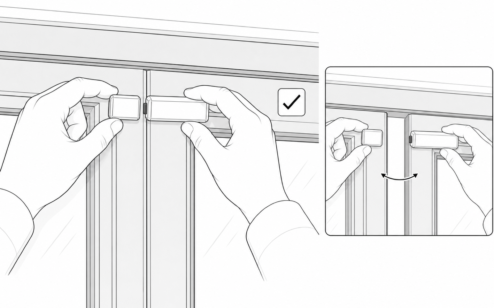
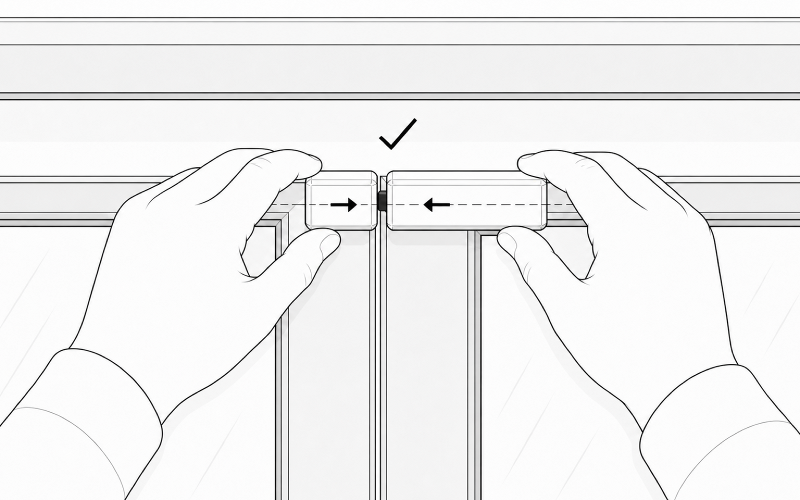
For a single door, position the sensor body on the moving door and the opposing block on the fixed frame. For a double-swing or double-sliding door, position the sensor body on one moving leaf and the opposing block on the other moving leaf. Close the door to confirm that the opposing block fully presses the activation button inward, then open it to confirm that the button releases freely.
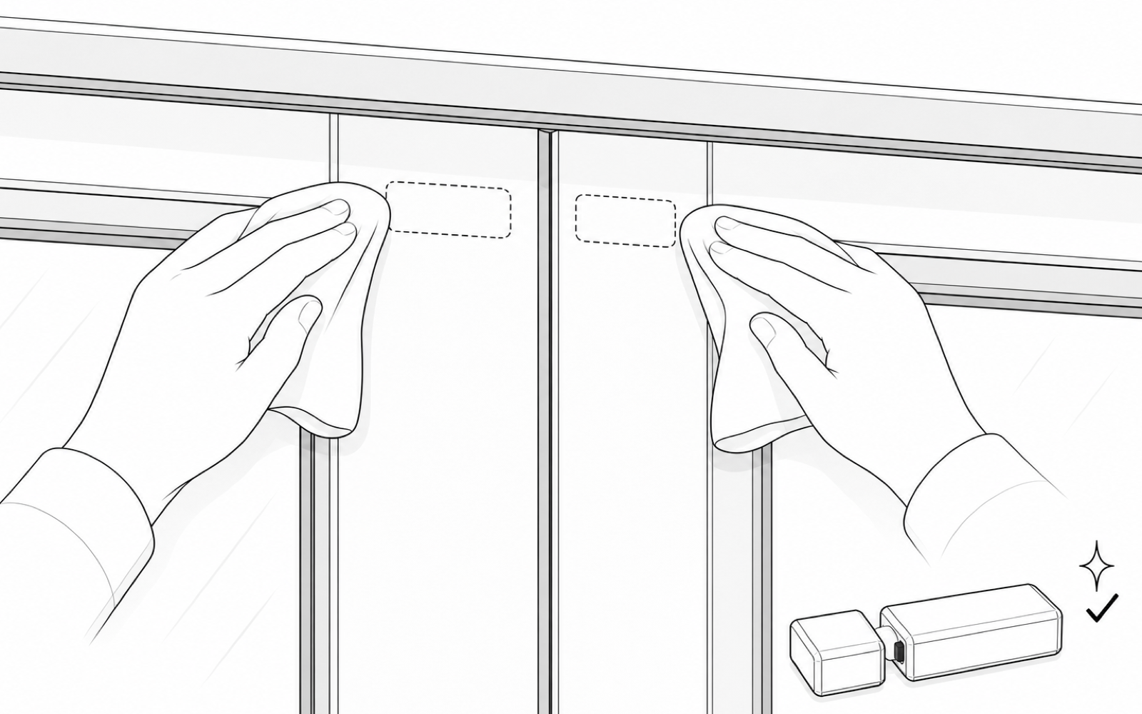
Clean the marked mounting locations on the door and frame. Remove dust, oil and moisture using a cleaner approved for both finishes, then allow the surfaces to dry completely.
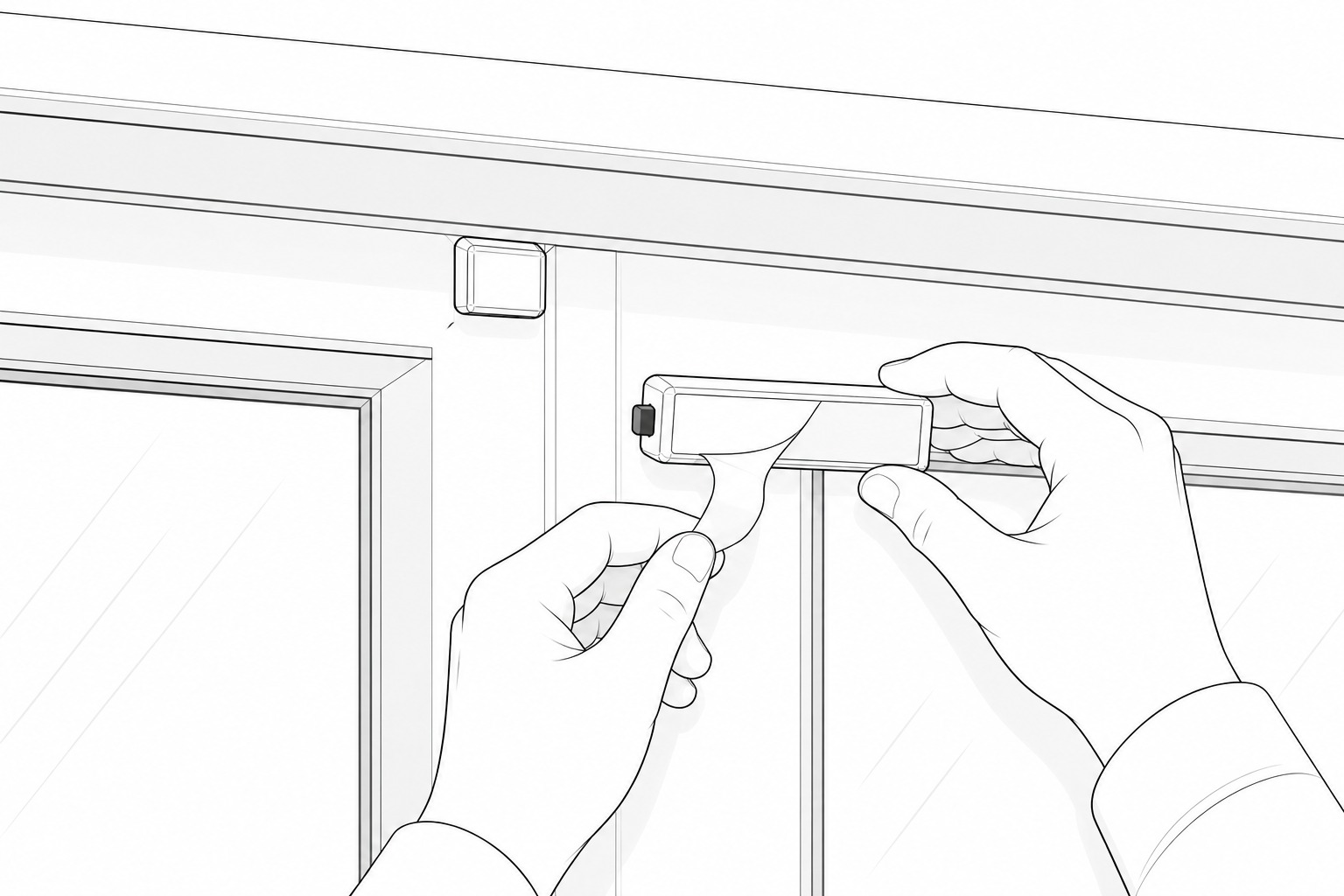
Once the positions are approved, carefully peel the protective liner from the adhesive on each component without touching the exposed bonding surface.
Place both components onto their marked positions, align the opposing block squarely with the activation button and apply firm, even pressure for 30 seconds.
After the adhesive has cured, close and open the door repeatedly and confirm the intended event reaches the paired hub or I/O module from the final position.
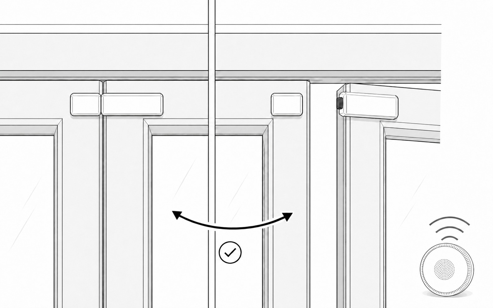
Use the selected receiver guide, then verify the complete alarm path.
Follow the receiver-specific guide for enrollment, zone naming, success indications and removal.
Do not hand over the installation until the complete event path works reliably from every final position.
Use these states to verify the physical product and connected-system response.
| State | Door Sensor | Expected system behavior |
|---|---|---|
| Door opened | Opposing block moves away and the activation button releases. | Opening action generates and transmits a 433 MHz RF event. |
| Door reclosed | Opposing block presses the activation button inward again. | Closing action generates and transmits a second 433 MHz RF event. |
| Armed while open | The sensor remains in the open state when the zone is armed. | Reclosing the door transmits an event and triggers the alarm for the armed zone. |
| Mini Alarm Hub and app | No local control is required at the sensor. | The app shows the real-time open or closed state whether the system is armed or disarmed. |
| Wireless I/O Module | Each opening or closing action transmits an event. | The module response follows the configured integration and zone rules. |
Resolve installation, power and communication faults before replacing the product.
| Symptom | Likely cause | Action |
|---|---|---|
| No event when door opens | Sensor not enrolled, receiver unavailable, weak RF path or incorrect mechanical activation. | Test near the receiver, confirm enrollment and inspect the final installation geometry. |
| Intermittent alerts | Weak radio conditions, metal shielding, unstable mounting or marginal activation. | Repeat tests at the final position and correct mounting or receiver location. |
| False or repeated alerts | Movement, obstruction, misalignment or unsuitable mounting surface. | Inspect the protected point, remove interference and remount if required. |
| Adhesive begins lifting | Contaminated surface, insufficient cure, unsuitable substrate or incorrect adhesive. | Remove safely, prepare again and remount using the approved bonding system. |
| Wrong device shown | Incorrect zone naming during commissioning. | Correct the device name and repeat the complete functional test. |
Current product values from the approved datasheet and dimension diagram.
| Item | Value |
|---|---|
| Product code | AG-ODR-100 |
| Dimensions | 110 × 28 × 16 mm when pressed inward |
| Weight | 38 g |
| Operating temperature | -20°C to 55°C |
| Storage temperature | -20°C to 55°C |
| Working humidity | ≤99% RH |
| Power | Self-powered |
| Shell material | PC |
| Installation | Surface mount |
| Transmission | 433 MHz RF |
| Transmission range | Up to 80 m outdoors; up to 25 m indoors |
| Durability | >100,000 cycles |
Routine inspection and functional testing remain required throughout the system life.